Joint Detail: The Rolled Groove O-Ring Gasket Joint
In many industries, O-Rings are commonly used in machinery, parts, and joints. The circular-shaped gasket can be utilized in static or dynamic applications and is easily manufactured, inexpensive, and dependable, making it one of the most widely used seals in machinery across the globe.
In infrastructure, the Rolled Groove O-Ring rubber gasket joint provides an economical, non-welded method for joining steel water transmission pipe (AWWA C200). They are suitable for a variety of buried pipeline applications, with a rated working pressure equal to the pipe class for most typical water transmission applications. With over four decades of field-proven performance, Northwest Pipe’s O-Ring gasket joint systems currently connect millions of linear feet of steel water pipe across North America.
Basis of Design
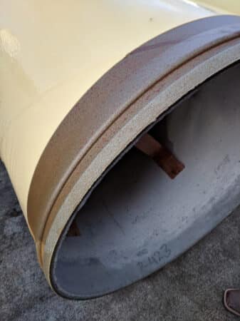
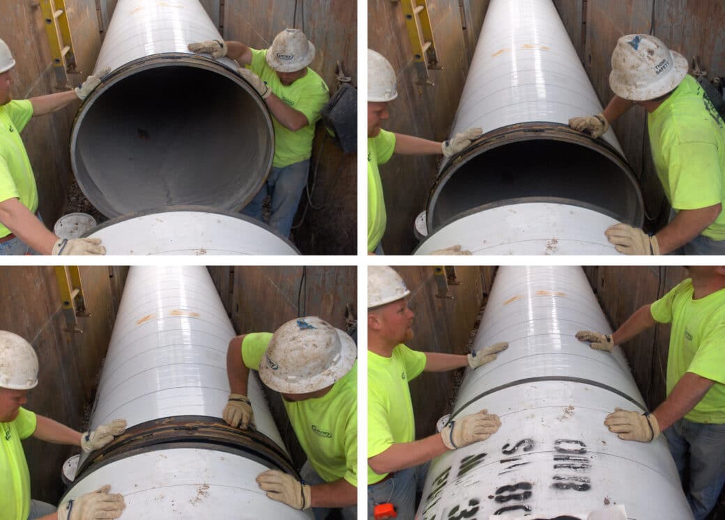
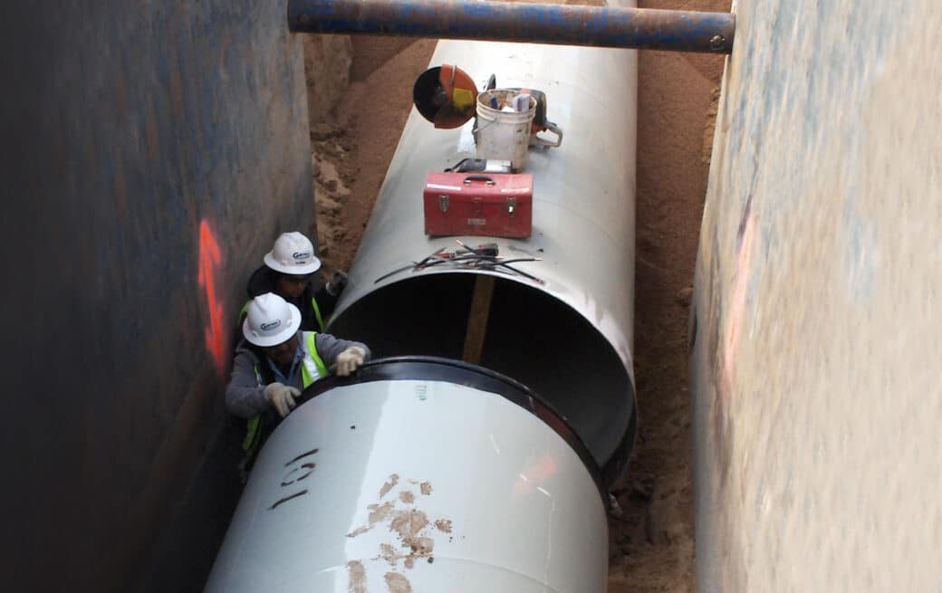
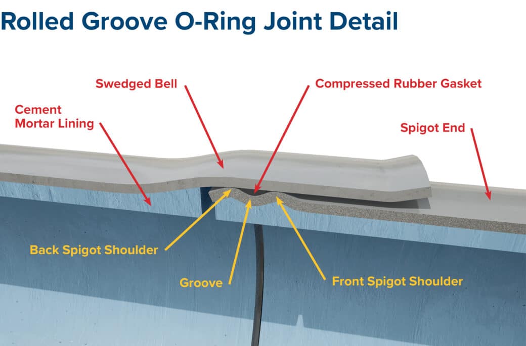
The Rolled Groove O-Ring Gasket Joint consists of an O-Ring gasket used with a bell and spigot joint. The bell end is flared to facilitate the insertion of the spigot. The spigot end includes a formed groove that retains the O-Ring gasket. When the spigot end is inserted into the bell end, the O-Ring gasket compresses against the steel surfaces to form a watertight seal. The O-Ring gasket is then confined within the groove annular space. The O-Ring gasket joint is self-centering upon assembly and does not require attachments or other formed shapes welded to the pipe end. The compression of the gasket within the groove forms the joint’s watertightness, not the water pressure within the pipe cylinder. Specifics of O-Ring standards can be found in AWWA Standards C200 and AWWA M11.
History and Background
The earliest patent for the O-Ring dates back to 1896, belonging to an inventor in Sweden. In the US, the first patent for the O-ring was filed in 1937 by a Danish-born machinist. O-rings are used in many industries including transportation, aerospace, medical, electronic, and food and beverage manufacturing.
The use of O-Ring gaskets in pipe joining systems dates to the 1930s. By the 1950s, a number of steel water pipe manufacturers in the eastern United States offered versions of the O-Ring gasket joint. These early O-Ring gasket joints were usually comprised of a cold-formed bell and a spigot that relied on a bar which was welded to the pipe to retain the O-Ring gasket, in lieu of today’s formed groove. In 1956, the Beall Pipe & Tank Corporation, a predecessor of Northwest Pipe Company, began offering a true, formed groove O-Ring gasket joint pipe.
Throughout the history of O-Ring gasket joints, Northwest Pipe and our affiliated companies have conducted many controlled tests. Testing programs have demonstrated the joint’s ability to operate at more than double the recommended angular deflection, with repeated pressure cycling, and with damaged gaskets. We have tested the Rolled Groove O-Ring joint to failure in excess of 760 psi, and in many cases, the steel in the pipe cylinder went into a yield condition before significant gasket joint leakage occurred.

Manufacturing Methods
In today’s manufacturing processes, the bell is usually formed by the swedge method in which the end of the pipe is sized over a plug die, during standard pipe hydrotesting operations. The use of a die ensures a smooth radius and tight fit. The spigot end, which includes the groove to retain the O-Ring gasket, is formed by rotating the pipe end between a set of matched rolling dies. Any spiral-weld seam within the joint configuration is ground flush prior to end formation and is nondestructively tested upon completion using either dye-penetrant or magnetic-particle methods. The O-Ring gasket is produced using a variety of manufacturing techniques like extrusion, compression molding, injection molding, transfer molding, or machining. Northwest Pipe employs gaskets made from a synthetic rubber blend per AWWA C200 requirements.
Rated Working Pressure
Because the O-Ring gasket joint is formed integrally into the pipe cylinder itself, the joint has a rated working pressure equal to the class of pipe, plus a standard allowance for surge or transient conditions equal to the pipe pressure class.
Angular Deflection
The Rolled Groove O-Ring gasket joint can be offset or “pulled” to a maximum of 1 inch. This allows for long–radius curves in pipeline alignment as well as minor offsets during pipeline construction.
AWWA Standards
Design and manufacturing of bell-and-spigot O-Ring gasket joints are in accordance with AWWA C200-17, paragraphs 3.6.6 – 3.6.6.3 and AWWA Manual M11, paragraph 8.1.
Benefits of the O-Ring Joint:
- Economical, non-welded method of joining buried steel water pipe.
- Field welding or other means of restraint required only in areas of thrust per AWWA M11.
- Trusted, cost-efficient pipeline installation.
- Joint flexibility allows angular deflection for long-radius curves and minor field alignment changes.
- Non-rigid joints accommodate some differential ground settlement after pipeline installation.
- Joint rated for pressure class of the pipeline.
Best Use for:
- Steel water pipe systems under 78” in diameter. Consult our sales/engineering team for pipe larger than 78”.
- Systems such as raw or potable water transmission mains, wastewater force mains, irrigation lines, or penstocks.
- Pipeline with long radius curves.
- Installation sites with potential settlement or subsidence soil issues.


 >
>
